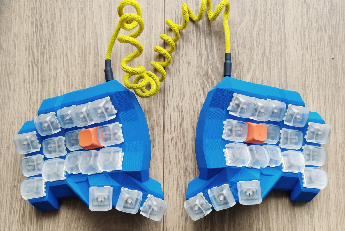
This guide provides step-by-step instructions for hand-wiring a split-keyboard. A 36-key Dactyl Minidox keyboard using Raspberry Pi Picos(RP2040 ) and KMK Firmware.
This build uses a “Visual Flow” wiring technique, The right half of keyboard is wired as the left half flipped around. See the visual wiring matrix under. This allows the firmware to remain simple and identical on both sides.
Prerequisites
Materials
| Product | Variant | Quantity | |
|---|---|---|---|
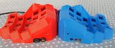 | 3D Printed Case | Dactyl Minidox | 1 Left, 1 Right |
 | Raspberry Pi Pico Board RP2040 | TYPE-C/MICRO with pins | 2 pcs |
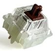 | Switches | Type MX. Brown, blue or your choice | 40 pcs |
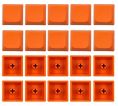 | Keycaps | Type MX | 40 pcs |
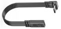 | USB M-F Extension Cable | 5 cm, male TYPE-C/ MICRO | 2 pcs |
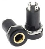 | Audio Jack Socket | PJ392A 3.5MM | 2 pcs |
 | 4 Pole TRRS Male to Male | 3.5MM | 1 pcs |
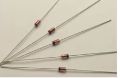 | 1N4148 Switching Diodes | 100 pcs | |
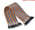 | Dupont Jumper Wires | 40 cm, female to female | 20 wires |
 | High Temperature Heat Tape | 15 mm | 1 roll |
Tools
- Soldering iron and solder
- Glue gun and glue sticks
- Wire strippers/cutters
- Tweezers
- Multimeter (optional, for debugging)
Testing and preparing your Pi Picos(controllers)
Before you begin, I recommend to get your Pi Picos ready to rock.
Follow the instruction on the KMK get started page to make sure you controllers are tested and up and running. Do the same procedure on both controllers before you start the assembly
Hardware Assembly
1. Wiring the Matrix
You will wire a 5-column x 4-row matrix on each side.
The Golden Rule of this Build: Wire the right half as the left half flipped around.
Wiring Steps
- Rows: Solder the diodes to the right pin of every switch. Connect the other end of the diodes horizontally. I hope the picture under clarify more than this simple words.
Diode Direction
The black band (cathode) must point away from the switch and towards the controller row wire.
Here the rows consist of diodes soldered together(Don’t do as mee. It is easier to solder the “diode” rows before the columns)
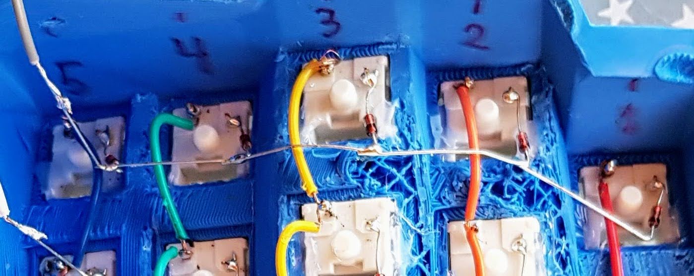
- Columns: Solder wires connecting the left pin of every switch vertically(Red, orange, yellow, green and blue colored wires on picture)
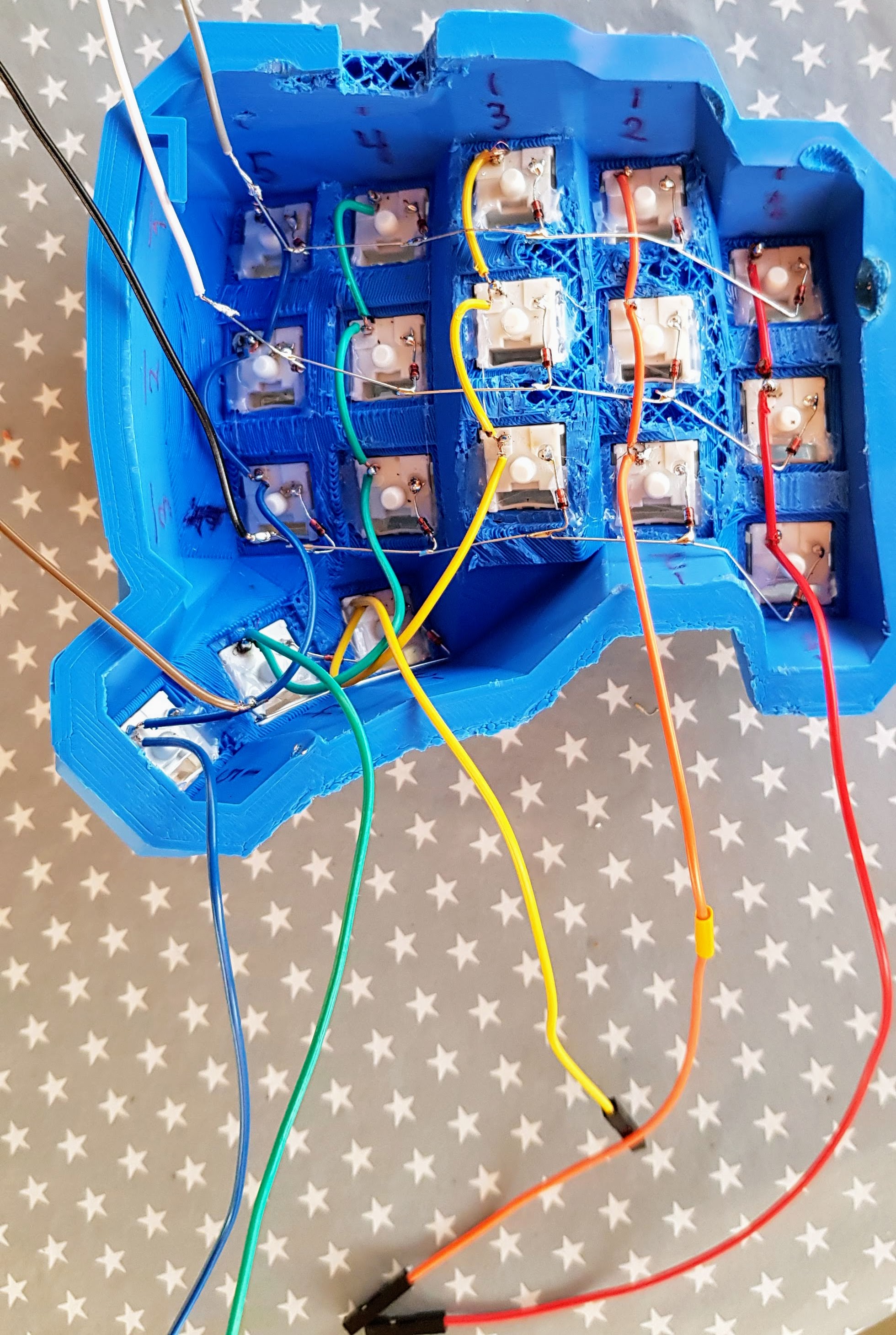
- The rules for soldering rows and columns to switches, are the same for both sides of keyboard(The pictures shows the left side of the keyboard)
- Rows: solder always on left pin of switch
- Columns: solder always on right pin of switch
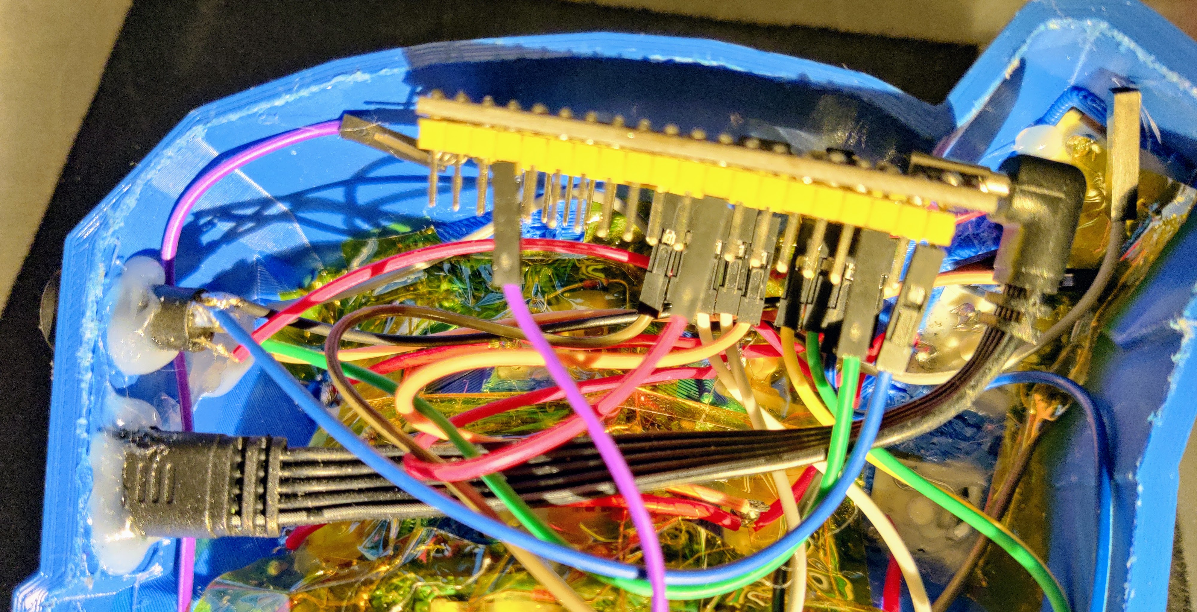
2. Connecting the Controller
Look at the picture above and under, the columns and rows are prepared with female DuPont wires, that makes it easy to connect to to a controller with pins. That makes it easy to reconnect rows/cols to controller if you do some mistakes. It also makes it easy to switch controller later on for an upgrade.
Connect the matrix rows and columns to the Raspberry Pi Pico using the following pinout.
Note
This pinout applies to BOTH the Left and Right controller.
| Function | Visual Position | Pico Pin |
|---|---|---|
| Col 1 | Pinky | GP2 |
| Col 2 | Ring | GP3 |
| Col 3 | Fuck you | GP4 |
| Col 4 | Pointer | GP5 |
| Col 5 | Inner Column | GP28 |
| Row 1 | Top Row | GP6 |
| Row 2 | Home Row | GP7 |
| Row 3 | Bottom Row | GP8 |
| Row 4 | Thumb Cluster | GP9 |
3. Split Communication (TRRS)
Connect the TRRS breakout boards to establish communication between the halves. We use a single-wire data connection (PIO).
Note
This pinout applies to BOTH the Left and Right TRRS connector/controller.
- Tip (T): Connect to VBUS (any VBUS pin).
- Ring 1 (R1): Connect to GP1 (Pin 2).
- Sleeve (S): Connect to GND (any GND pin).
If these terms on the TRRS connectors does not say nothing to you, just connect them on TRRS connectors that are the same on both sides of keyboard.
Electrical Hazard
NEVER plug or unplug the TRRS cable while the USB is connected to the computer. This can short the power pin to the data pin and permanently destroy your Pico. Always unplug USB first.
4. Identity Jumper (Right Side Only)
To allow the code to automatically detect which side is which, you must add a physical “jumper” wire to the Right Controller only.
- Right Pico: Connect a female to female DuPont cable connecting GP21 directly to a GND pin of choice.
- Left Pico: Nothing to do here.
In the documentation for KMK split keyboards, there is described that you have to rename the drives for Circuit python, for both sides. That is not necessary with this build.
Firmware Configuration
1. Installing Circuit Python and KMK
I assume that you have done this already.
Follow the instruction on the KMK get started page to make sure your Pi Picos are tested and up and running. Do the same procedure on both Pi Picos
2. The Code (code.py)
Copy the code below into the file named code.py, overriding the test code you made in the previous step. Do it on BOTH drives, Left and right.
When using and testing the full keyboard. The USB cable could always be connected to the left keyboard half.
print("--- STARTING KEYBOARD ---")

import board
import digitalio

from kmk.kmk_keyboard import KMKKeyboard
from kmk.keys import KC
from kmk.scanners import DiodeOrientation
from kmk.modules.split import Split, SplitType, SplitSide
from kmk.modules.layers import Layers


# --- 0. PIN DEFINITIONS ---
# All GPIO pins are defined here as constants for readability and easy maintenance.
# If you change the wiring, you only need to update the values in this section.

# General Pins
SIDE_DETECTION_PIN = board.GP21  # Jumper to GND on the right side to identify it.
SPLIT_UART_PIN = board.GP1       # Pin used for UART communication between halves.

# Column Pins (based on finger hints, from outside to inside)
PINKY_COL_PIN         = board.GP2   # Col 1
RING_FINGER_COL_PIN   = board.GP3   # Col 2
MIDDLE_FINGER_COL_PIN = board.GP4   # Col 3
INDEX_FINGER_COL_PIN  = board.GP5   # Col 4
INDEX_INNER_COL_PIN   = board.GP28  # Col 5

# Row Pins (from top to bottom)
TOP_ROW_PIN    = board.GP6   # Row 1
HOME_ROW_PIN   = board.GP7   # Row 2
BOTTOM_ROW_PIN = board.GP8   # Row 3
THUMB_ROW_PIN  = board.GP9   # Row 4


# --- INITIAL SETUP ---
keyboard = KMKKeyboard()
keyboard.modules.append(Layers())

# --- 1. JUMPER DETECTION ---
jumper = digitalio.DigitalInOut(SIDE_DETECTION_PIN)
jumper.direction = digitalio.Direction.INPUT
jumper.pull = digitalio.Pull.UP

is_right = False
if not jumper.value:
    is_right = True


# --- 2. SPLIT CONFIGURATION ---
split = Split(
    split_type=SplitType.UART,
    data_pin=SPLIT_UART_PIN,
    use_pio=True,
    uart_flip=True
)

if is_right:
    split.split_side = SplitSide.RIGHT
else:
    split.split_side = SplitSide.LEFT

keyboard.modules.append(split)

# --- 3. PINS & MATRIX (The Fix) ---
# We use the SAME pin order for both sides.
# Order: GP2 -> GP3 -> GP4 -> GP5 -> GP28
col_pins = (
    PINKY_COL_PIN,
    RING_FINGER_COL_PIN,
    MIDDLE_FINGER_COL_PIN,
    INDEX_FINGER_COL_PIN,
    INDEX_INNER_COL_PIN,
)
row_pins = (
    TOP_ROW_PIN,
    HOME_ROW_PIN,
    BOTTOM_ROW_PIN,
    THUMB_ROW_PIN,
)
# Matrix
keyboard.col_pins = col_pins
keyboard.row_pins = row_pins
keyboard.diode_orientation = DiodeOrientation.COL2ROW

# --- 4. KEYMAP ---
keyboard.keymap = [
    [
        # Left Hand (Cols 1-5)                     # Right Hand (Cols 1-5)
        KC.Q,  KC.W,  KC.E,    KC.R,    KC.T,      KC.Y,   KC.U,    KC.I,    KC.O,   KC.P,    # Row 1
        KC.A,  KC.S,  KC.D,    KC.F,    KC.G,      KC.H,   KC.J,    KC.K,    KC.L,   KC.SCLN, # Row 2
        KC.Z,  KC.X,  KC.C,    KC.V,    KC.B,      KC.N,   KC.M,    KC.COMM, KC.DOT, KC.SLSH, # Row 3

        # Thumbs (Row 4)
        KC.NO, KC.NO, KC.LCTL, KC.LSFT, KC.SPC,    KC.ENT, KC.BSPC, KC.LALT, KC.NO,  KC.NO,
    ]
]

if __name__ == '__main__':
    keyboard.go()